

1. 1. definition of the trips and travel times
1.1. 1.1. general information
The definition of trips for the trains is based, as with with bus lines, on the function "tracks and trips" in OMSI editor. It is important to use type 1 trips! Do not use the function "StationLinks"!
The type 1 - trip function creates tracks and following that also trips with stations with one or more timetable profiles.
The first particularity of the trip function concerns the "busstop" cubes, which you should put at the desired stop position in front of the train, in the centre of the rail track. If the first part of the train (normally the train engine), goes backwards while testing (exemple: steam engine with the chimney/stack pointing in the wrong direction), you have to put the busstop cube the other way round.
NB: The busstop cube always needs to correspond to the "technical direction" of the first part of the train which isn't always the real direction.
train with a steam engine which points towards the wrong direction: the busstop cube is set on the opposite site of the actual direction of the train (blue arrow).
train with a steam engine which points towards the right direction: The busstop cube is set to the direction of travel (blue arrow).
1.2. 1.2. Special feature for shuttle train operations:
If you want to realise a shuttle train operation (the train changes direction at a visible terminus), the station has to be equipped with two bus stop cubes on the same track. One of them points in the direction of travel of the incoming train and marks the train's stopping point. This bus stop cube is assigned to the trip for the arriving train.
In addition, you need to set annother bus stop cube in the opposite direction exactly at the end of the train. This second bus stop cube needs to be assigned to the trip for the departing train.
In addition, the checkbox "Train reversed by default" must be activated for this trip.
The checkbox framed in red needs to be active for the trip of the departing train during shuttle train operation.
2. 2. definition of the deployment of trains
Each train set you want to use has to be defined in the ailists.cfg of the map by using the command [aigroup_2]. If you want to use different train sets for different runs, you need to set up a separate [aigroup_2] for each of these runs.
Example: use of different train sets for different runs:
[aigroup_2]
Dampfzug_hin
Steinkirchen V2
trains\BR99.22_Lehntalbahn_Steinkirchen.zug
[end]


[aigroup_2]
Dampfzug_rück
Steinkirchen V2
trains\BR99.22_Lehntalbahn_Steinkirchen__rueck.zug
[end]In contrast to the implementation of road traffic in OMSI 2 (.bus, .ovh), ailist entries for trains refer to .zug files. These .zug files are stored in the trains\ directory in the OMSI main directory.. They can easily be created using any text editor. The structure of the files is best explained by the following example:
vehicles\BR99.22\BR99.22.ovh
0
vehicles\Schmalspurbahn_Steinkirchen\Personenwagen_end.ovh
1
vehicles\Schmalspurbahn_Steinkirchen\Personenwagen_Bar.ovh
0
vehicles\Schmalspurbahn_Steinkirchen\Personenwagen_AB.ovh
1
vehicles\Schmalspurbahn_Steinkirchen\Personenwagen_end.ovh
0
In that code, the cariage order of a narrow-gauge steam train is shown. This train consists of a class 99.22 locomotive, a rear coach, a bar coach, a compartment coach and another rear coach. The individual vehicles are defined one after the other, so that the respective path to the .ovh file is given. A 0 or 1needs to be entered in the respective following line. The 0 or 1 indicates whether the vehicle is arranged forwards (0) or backwards (1) in the direction of travel.
In the given example, the steam locomotive is arranged forwards, followed by a rearward end coach, then a forward bar coach, and so on. The standard "forward" orientation of a rail vehicle is always set by the creator of the vehicle. In case of doubt, try it out and turn individual vehicles again by exchanging 0 for 1 or vice versa, if the coach points towards the wrong direction in the player mode.
3. 3. creation of runs
The usual mechanisms known from the creation of bus runs in OMSI 2 also apply to the creation of train runs. If trains spawn or disappear outside the area of the map visible to the players, the corresponding trips of the run can be set one after the other without any problems, even without "SmoothTrans". Thus, neither the construction of a track loop nor the implementation of a shuttle train operation is necessary in these cases.
4. 4. railway technology in OMSI 2
4.1. 4.1. general information:
The railway technology in OMSI 2 is controlled via signal routes. OMSI 2 also contains a basic function for railway operation with switches and level crossings, but without signals. You should not use this basic function if you want to use functioning switches, signals and level crossings. As soon as the first signal route is created on a map, OMSI 2 switches the entire map to the extended railway technology mode, which is described in this article. All signal routes are stored in the map folder in the file signalroutes.cfg. To reset to the basic mode, close OMSI 2, open the signalroutes.cfg file with a text editor and delete the entire content of that file.
Be careful! The signal routes are a fiddly system. Only create signal routes after you've set all track paths (incl. level crossings and switches) in a final state. Changing track paths in existing signal routes can lead to errors in the signal routes and thus disrupt the entire railway traffic!
4.2. 4.2. switches
In OMSI 2, in addition to the real switches that are required for correct implementation, there are also fake switches. Real swtiches can be recognised by the green lettering "<ED_Switch>" in the editor. If, for example, "traffic light" is written there instead, these switches are not compatible with the signal route system.
4.3. 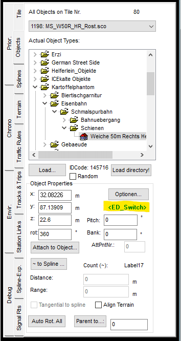
a real, functional switch with the correspondant label.
4.4. 4.3. level crossings
Level crossings function in OMSI 2, from a technical point of view, like traffic light intersections . Therefore, a corresponding crossing object is required, which contains both - the corresponding rail paths and the streets (with paths for humans). This then includes a traffic light circuit that regulates the mutual release of the respective paths. The closing of the level crossing is triggered by a request circuit for the trains. Further information on the timing for closing the level crossing follows in the further course of this article.
4.5. 4.4. signals
Similar to the switches, it is also important to ensure that only real, functional signals are used for the signals. These are marked in the editor by the green lettering "Signal". Signals that are instead marked with the entry "traffic light" are not suitable.
A real signal with the correspondant label.
In general, a distinction must be made between main signals and approach signals. Main signals indicate whether a train is allowed to pass this signal either at the maximum permitted speed (signal is green), at reduced speed (40 km/h, signal is green/yellow) or not at all (signal is red). As a rule, they stand at a sufficient distance before switches or divide longer double-track sections into so-called "blocks". Approach signals are located at a braking distance, usually 750 to 1000 metres, in front of the main signal and announce the position of the next signal to the train crew.
This description of the principles of the German signalling is simplified. There is a lot of further information on this topic on the internet, e.g. on the website http://stellwerke.de/signal/deutsch/index.html (external link - only available in German) You can also search for explanation about it in English by googling.
4.6. 4.5. signalroutes
In order to use the signals in a functional way, you have to create signal routes. Each signal route consists of at least two path segments and a main signal and can, optionally, also contain information about the next main signal and the corresponding approach signal. The signal routes are created via the menu on the right edge of the editor window in the "SignalRts" tab. A new signal route is created via the "Add Route" dialogue. In the "Add / remove (+Shift) Paths" mode, the path segments whose release is to be controlled by the associated signal are now first checked in sequence.
In other words, a track segment is defined to be secured by a main signal located at the beginning of this track segment. Therefore, the track segment needs to start at the corresponding signal and lead at least as far as the point to be secured behind it, e.g. a switch or a level crossing, but mostly as far as the next main signal. The first path segment you click on, is the first path segment that is not used by the train, when the signal is red. The train stops on the last preceding path segment. For an appealing visual design, it is recommended to place the signal a few metres behind the separation point of two path segments, so that the front of the train stops at some distance from the signal.
The first path segment starts next to the position of the main signal. Therefore, the train stops with a little distance in front of the signal.
By clicking on the path segments, the track section to be monitored by the main signal is determined. It is important that the path segments are selected in the correct order in which the train will travel. OMSI 2 does not perform a logic check here, i.e. if you click carelessly, rail paths that are not directly adjacent and even car and human paths can be clicked. You can deselect the path segments clicked on by mistake by clicking on them while holding down the Ctrl key.
When the track section to be monitored is defined, select the "Set Signal" mode. Now click on the corresponding main signal. In the area "Sel. Signal Route Properties" (lower section of the menu on the right edge of the editor window) you can determine which status the signal should display when the corresponding track section is released. Here you can distinguish between "1" for "green" or "2" for "green/yellow". Depending on the design, the signal may only display "green". In this case, only "1" can be selected here. In the field "Spd. Limit (0 if none)" you can select a speed that should be valid for passing the signal. If the default value "0.0" is left here, the train will follow the standard speed that was assigned to the track path via the traffic rules.
In the mode "Add / remove (+Shift) next main Signal", the main signal can now be selected by left-clicking, which is the next signal on the track path, i.e. which is controlled by the following signal route. In the "Add / remove (+Shift) Dist. Sig. for next Sig." mode, the approach signal associated with the next signal just selected can be selected by left-clicking.
4.7. 4.6. the right timing
In order to provide the player with a realistic picture of the switching processes of switches, level crossings and signals, the correct timing is a decisive factor. For example, the main signal in front of a level crossing should only switch to "green" when the level crossing is completely closed. Tricks may have to be used to achieve this. Ultimately, there is no way around testing the settings made in the editor multiple times in player mode and then readjusting them in the editor. This step can be frustrating and very time-consuming, but for perfectionists it is worth the effort.
First of all, it is important to have a basic understanding of the timing of signal routes. We imagine two consecutive signal route sections ( A and B ). OMSI 2 works as follows: As soon as the train passes the first path segment of section A, the check for section B is triggered. This check includes the switching of all switches located in section B to the correct position and the triggering of a request for all level crossings located in section B. The traffic lights of the level crossing are switched on and off. The level crossing's traffic light switching thus jumps to the point intended for the request case at this moment. As a rule, this means that the red lights start flashing and a little later the barriers close. Directly with the start of the test of section B, however, OMSI 2 also switches the main signal of section B to the intended driving position.
Depending on the location, this can lead to a main signal placed directly in front of the level crossing signalling "Go" to the approaching train, although the barriers are still open and there are still cars on the tracks. Even without a signal directly present, it can happen that the train reaches the level crossing too early and thus, from the player's point of view, there is not enough buffer time between the closing of the barriers and the arrival of the train at the level crossing. To avoid such unpleasant situations, there are some approaches that can be used to optimise the timing:
1. The line speed in the approach to the level crossing can be reduced by means of traffic rules, so that more time elapses between the triggering of the request and the arrival of the train at the level crossing.
2. There must be a sufficiently long track section between the spawn point of the train at the tile boundary or start of the signal route on the one hand and the level crossing on the other hand, so that the request is triggered early.
3. Additional hidden signals with associated signal routes can be interposed.
Approach 3 avoids the time sequence described above when switching the signal routes. In relation to the original example, three signal routes are required instead of two, i.e. sections A, B and C are created. In OMSI 2, the situation must be set up as follows: Section A is regularly equipped. This section is followed by section B. Section B consists of a main signal, which is invisible to the player and hidden behind a backdrop of houses, a backdrop or similar, and the adjoining path segments including points and level crossing. Directly after that, i.e. from the first or second path segment behind the level crossing or the switch, up to the next main signal, is section C. The main signal of section C is optically hidden behind a house backdrop or similar. The main signal of section C is visually placed at the beginning of section B. Since OMSI 2 only triggers the checking and switching of section C when section B is fully secured for the train, i.e. the level crossing is also closed, the signal is only switched to green then.
Principle representation for direction of travel from bottom to top. Signal C is technically assigned to the section shown in green and only switches to "drive" when the level crossing in section B, shown here in red, is closed.
4.8. 5. technical limits
OMSI 2 is and remains a bus simulator and not a train simulator. Experience shows that certain operating situations cannot be implemented. For example, the operation of a single-track line with train crossing in a junction station is unfortunately not feasible. Trains in OMSI 2 sometimes spawn with a significant delay or do not wait for the idle times at the stations despite the corresponding characteristics set in the time profiles. Breaking the trip of a train in the crossing station into two different trips, on the other hand, leads to the second trip not triggering the associated signal routes and thus preventing a continuation of the journey. Especially the spawn behaviour should be tested intensively in player mode in different situations and with different sight distances (number of neighbouring tiles). It is of no use if the same standard situation is tested again and again and optimised for an error-free representation of the train operation and then the player encounters a completely different situation when driving a bus circuit on the railway line and finds a malfunction there. The only thing that helps here is try n'error.
4.9. 6. conclusion
This wiki article presents the experience gained from setting up rail traffic on the map Steinkirchen V2. It does not claim to be complete or correct. The general principle of caution applies! We encourage you to backup your construction regularly! The author assumes no liability.
And now: Aave fun and success with the implementation of railway technology in your maps!
")